Smart Warehouse Technology
How angle sensor technology mounted directly on the forklift tilt cylinder is transforming load stability monitoring, pallet placement accuracy, and predictive maintenance across Colombian manufacturing and logistics facilities.
In this article: Why Angle Sensing Matters | Cylinder Structure | Sensor Mounting Positions | Material System | Integration Architecture | Load Level Detection Logic | Regulations | FAQ
Why Mast Angle Monitoring Is Central to Smart Warehouse Automation
In automated and semi-automated warehouse facilities across Colombia — from manufacturing distribution centers in Bogotá’s Zona Industrial to high-bay racking operations in Medellín’s CEDI logistics hubs — the tilt cylinder has historically been a passive mechanical component: it moves the mast forward and backward on command, and that is all the warehouse management system knows about it. Smart warehouse architecture changes this relationship fundamentally. When an angle sensor is integrated directly into or adjacent to the forklift tilt cylinder assembly, the mast inclination angle becomes a live data point that the warehouse management system, forklift telematics platform, and safety interlock controller can all access in real time.
This single data point — mast angle — unlocks capabilities that were previously only achievable with expensive overhead laser scanning or camera-based vision systems. It tells the WMS whether the forks are level before a pallet is picked or deposited, whether the load is being transported with the mast at the correct rearward tilt angle for stability, and whether the operator is tilting forward under load in a way that moves the load’s center of gravity beyond the stability triangle boundary. All of this information flows from the position of one cylinder: the forklift tilt cylinder whose stroke position, combined with the known geometry of the mast linkage, gives a direct calculation of the mast angle at any moment during operation.
Manufacturing Structure of the Forklift Tilt Cylinder
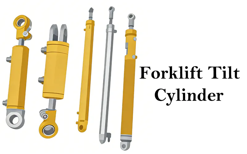
Understanding which structural features of the tilt cylinder are relevant to angle sensor integration starts with a clear picture of the cylinder’s anatomy. The tilt cylinder is a double-acting hydraulic actuator: oil pressure on the bore side extends the rod and tilts the mast forward; pressure on the rod side retracts and tilts backward. The physical stroke of the rod — the distance it travels between full retraction and full extension — maps directly to the angular range of the mast. For a typical counterbalanced forklift with a 6° forward and 12° backward tilt range, the rod stroke encodes 18° of angular travel. Knowing the rod position at any moment gives the mast angle with straightforward trigonometric calculation once the mast pivot geometry is established during the sensor commissioning process.
Barrel and Bore
The cylinder barrel is a precision-honed seamless steel tube. For angle sensor integration, the barrel is also the primary reference surface: any dimensional variation in the barrel affects the accuracy of linear position measurement if a magnetostrictive or inductive position transducer is embedded in the barrel. Barrel straightness and bore cylindricity tolerances tighter than standard are specified for sensor-equipped cylinders to avoid measurement error caused by rod micro-deflection at stroke extremes.
Piston Rod
The chrome-plated piston rod is the moving reference element in a linear position measurement system. Rod surface continuity is critical: any chrome spalling, corrosion pit, or weld repair in the measurement zone will create false position readings. For cylinders fitted with external magnetostrictive transducers tracking a magnet embedded in the piston, the rod material must be non-magnetic (austenitic stainless or non-magnetic steel) in the sensor measurement zone to avoid interference with the magnetic position measurement field.
Front Gland
The front gland is the most common location for external angle sensor mounting brackets on the forklift tilt cylinder body. Its fixed position relative to the barrel and its structural rigidity make it the preferred anchor point for MEMS-based inclinometers that measure the absolute inclination of the cylinder body itself rather than rod stroke position. Sensor brackets welded or clamped to the gland must not introduce stress concentrations into the gland material that could cause gland seal leakage under the vibration loads of normal forklift operation.
Trunnion Pins and Mounting Brackets
The trunnion pins connect the cylinder to both the mast frame and the chassis, defining the pivot axes around which the cylinder rotates as the mast tilts. For sensor integration, the trunnion pin geometry is the kinematic datum from which the angular position calculation is built. If pin wear changes the effective pivot location relative to the sensor mounting point, the angular calculation accumulates an offset error that grows over the life of the pin. Scheduled pin diameter inspection is therefore a maintenance requirement in sensor-integrated forklift hydraulic tilt cylinder systems.

Material System and Sensor Compatibility
The material system of the forklift tilt cylinder directly determines which sensor technologies can be integrated without compromising either sensor performance or cylinder mechanical integrity. The interaction between hydraulic cylinder materials and electronic measurement systems is an engineering challenge that is underappreciated in many early smart warehouse retrofit projects, and it is where most integration failures originate.
Steel barrel and gland materials are ferromagnetic, which creates two issues for magnetic sensor types. First, the barrel itself will partially shield the magnetic field of a piston-embedded magnet from an external magnetostrictive transducer, requiring the transducer to be mounted in a non-magnetic adapter tube or positioned such that the field can pass through the barrel wall without significant attenuation. Second, magnetic field interference from nearby electric motors, battery packs, and inverter drives on the forklift creates background noise that MEMS Hall-effect sensors may misinterpret as position change if the sensor’s noise rejection threshold is set too low for the electromagnetic environment of the specific forklift model.
For cylinders in the EP-HCY series, which use carbon steel barrels with hard-chrome piston rods, the practical sensor choice for retrofit integration is a body-mounted MEMS inclinometer rather than a linear position transducer embedded in the cylinder. The MEMS inclinometer measures the absolute inclination angle of the cylinder body in the tilt plane, which maps to mast angle without requiring any modification to the cylinder internal components. This preserves the cylinder’s rated working pressure of 18.1 MPa and maximum withstand pressure of 27 MPa without any compromise, while providing the ±0.1° to ±0.5° angular resolution typically required for automated load level detection in smart warehouse pallet placement systems.
Angle Sensor Technologies and Their Mounting Positions
Four sensor technologies are commonly applied to tilt cylinder angle measurement in smart forklift systems. Each has distinct advantages and constraints relative to the cylinder structure, the forklift’s electromagnetic environment, and the data update rate requirements of the warehouse automation system it feeds.
| Sensor Type | Mounting Location on Cylinder | Typical Resolution | Update Rate | Primary Limitation |
|---|---|---|---|---|
| MEMS Inclinometer (2-axis) | Clamped to gland or barrel body | ±0.1° | 10–100 Hz | Vibration-induced error during mast travel |
| Magnetostrictive Linear Transducer | Internal barrel bore (OEM) or external tube | 0.01 mm stroke | Up to 1 kHz | Requires cylinder modification for retrofit |
| Inductive (LVDT) Position Sensor | External rod travel measurement | ±0.05 mm | 50–500 Hz | Sensitive to external vibration; cable routing |
| Rotary Encoder at Trunnion Pin | Trunnion pin bore of mast frame | 0.05° to 0.1° | Up to 1 kHz | Requires mast frame modification; pin wear |
Sensor selection for smart warehouse integration in Colombian manufacturing facilities should account for the facility’s electromagnetic noise level, the required data update rate for the WMS interface, and whether the integration is a retrofit to existing forklifts or a specification for a new machine build.
How Load Level Detection Logic Works in Practice
The operational logic of automated load level detection using the tilt angle signal is built around three distinct operational states that the smart warehouse controller monitors continuously during fork movement. Understanding these states and the angle thresholds that define them is essential for commissioning engineers and WMS programmers setting up tilt angle integration for the first time in a Colombian manufacturing facility.
When the mast angle falls within ±0.5° of true horizontal (as defined during the initial zero-calibration with a spirit level on the forks), the smart warehouse controller considers the forks to be in the level window. This is the condition that must be confirmed before the WMS authorizes the final descent of a load onto a pallet or racking level. If the forklift tilt cylinder angle sensor reports a value outside this window when the operator initiates the deposit command, the controller can generate a soft alarm — prompting the operator to correct the mast angle — or in fully automated guided vehicle systems, apply a trim correction to the tilt cylinder control circuit automatically.
During travel with a load, most forklift manufacturer guidelines specify a rearward mast tilt angle of 3° to 5° to shift the load’s center of gravity back toward the drive axle and improve dynamic stability. The tilt sensor on the forklift hydraulic tilt cylinder can enforce this as a travel safety condition: if the load weight detected by fork pressure sensors exceeds a defined threshold and the mast angle sensor reports insufficient rearward tilt, the smart controller can trigger an audible alert, log the event in the telematics system, or in integrated fleet management systems, note the safety deviation for supervisor review. This forms a key layer in the fall-prevention safety architecture for high-bay warehouses in Colombian manufacturing facilities.
When the operator holds the mast at a commanded tilt angle and the angle sensor reports slow unintended drift — typically 0.5° to 1.0° per minute under load — the smart warehouse controller can flag this as a forklift tilt cylinder drift condition. Tilt drift indicates piston seal internal bypass, a known failure mode of aging cylinder seal kits. By logging the drift rate over time, the telematics system builds a degradation trend that allows the maintenance team to predict when the cylinder will require seal kit replacement before it reaches the point of visible external leakage or a safety-critical mast drop. This is true predictive maintenance, made possible by the continuous angle signal from the sensor.

Integration Architecture for Colombian Smart Warehouses
Deploying angle sensor data from the forklift tilt cylinder into a working smart warehouse automation architecture requires decisions at four distinct levels: sensor-to-controller communication, controller-to-telematics gateway, gateway-to-WMS interface, and WMS-to-racking infrastructure (for facilities using active rack sensors or RFID pallet identification). Each level has technology options and trade-offs that need to match the existing infrastructure at the Colombian facility.
At the sensor-to-controller level, most MEMS inclinometers suitable for forklift tilt cylinder integration output either a CAN bus signal (SAE J1939 or CANopen, both standard in modern forklifts) or an analog 0–10V or 4–20 mA signal that feeds into the forklift’s existing I/O module. CAN bus output is strongly preferred for new implementations because it provides noise-immune digital communication, sensor diagnostics (fault codes and signal health status), and multiplexing with other sensor signals on the same bus wiring harness without adding cable runs. Analog sensors are appropriate for retrofit applications where the existing forklift controller lacks CAN expansion ports but has available analog inputs.
At the gateway-to-WMS level, the tilt angle data typically travels over the facility’s Wi-Fi network (IEEE 802.11ac or newer, with industrial-grade access points mounted on warehouse columns to provide continuous coverage across aisle movement) as part of a forklift telematics packet that includes fork height, load weight, speed, battery state, and operator ID. For Colombian manufacturing facilities without existing industrial Wi-Fi infrastructure, a phased deployment approach starting with Bluetooth-based local logging and periodic gateway upload is practical as a first step toward full real-time WMS integration.

Featured Product: EP-HCY-3 Forklift Tilt Cylinder
For larger counterbalanced forklift platforms deployed in Colombian manufacturing warehouse operations — where high-bay racking, heavy pallets, and automated load level detection requirements all come together — the EP-HCY-3 provides the structural specification needed for reliable, long-cycle-count service. Its working pressure of 18.1 MPa and maximum withstand pressure of 27 MPa support safe operation within the hydraulic circuit of 3 to 5 tonne counterbalanced forklifts, while the 174 mm stroke and 507 mm installation distance suit the wider range of mast tilt geometry found on larger frame forklift platforms commonly used in Colombian heavy manufacturing and steel distribution facilities.

EP-HCY-3 Forklift Tilt Cylinder
| Parameter | Specification |
|---|---|
| Working Pressure | 18.1 MPa |
| Max. Withstand Pressure | 27 MPa |
| Stroke | 174 mm |
| Installation Distance | 507 mm |
| Action Type | Double-acting |
| Recommended Sensor Mount | MEMS inclinometer on gland body (retrofit-compatible) |
Regulatory Compliance: Colombia and International Standards
Deploying tilt angle sensor systems on the tilt cylinder within Colombian smart warehouses involves compliance with a layered set of national and international regulations governing both the forklift’s hydraulic system and the electronic data systems collecting and acting on sensor data.
Under Colombia’s occupational safety framework, adding angle sensors and automated intervention systems to forklift hydraulics constitutes a modification of work equipment. Under Decreto 1072 de 2015, the employer must ensure that any modification does not reduce the machine’s original safety standard and must document the modification in the equipment’s technical file. If the sensor integration includes automated hydraulic intervention (auto-leveling trim of the tilt cylinder), this modification must be validated against the original OEM hydraulic system specification before deployment in any Colombian manufacturing facility.
EN ISO 3691-1 defines safety performance requirements for counterbalanced forklifts, including provisions for electronic systems that affect vehicle movement. Clause 5.6 of the standard covers stability requirements, and any electronic system that modifies tilt cylinder control logic — including angle-based interlock systems — must demonstrate that it does not compromise the stability performance defined in the standard. Colombian importers of EU-manufactured forklifts with integrated tilt sensor systems should verify that the CE technical file covers the sensor integration and automated tilt control functionality.
OSHA 1910.178 governs powered industrial trucks and is widely referenced by multinational corporations operating Colombian facilities. Section (e)(1) requires that forklifts only be modified with the manufacturer’s written approval. For sensor integration on the forklift tilt cylinder, this means obtaining manufacturer approval for any bracket welding or electrical connection to the cylinder or mast before deployment. Sensor systems using clamp-on (non-welded) mounting with sealed electrical connections that do not interrupt the OEM hydraulic circuit are generally achievable without manufacturer modification approval under this standard.
ISO 4413 specifies safety requirements for hydraulic systems in machinery. For sensor-integrated tilt cylinders, the standard’s provisions on pressure containment and fluid handling require that any sensor mounting bracket, cable feed-through, or position transducer housing attached to the cylinder body must not compromise the cylinder’s pressure boundary integrity. Sensor installations that drill into the barrel or add hydraulic fittings to tap cylinder pressure must demonstrate compliance with the burst pressure ratio requirements of ISO 4413 after modification. This is one reason why non-invasive external sensor mounting is strongly preferred for retrofit integration on existing cylinders in service.
Where the angle sensor data from the forklift tilt cylinder feeds into an automated safety interlock function — such as preventing forward tilt under load above a defined weight threshold — IEC 61508 provides the framework for evaluating the Safety Integrity Level (SIL) required for that function. In most warehouse contexts, a tilt angle interlock would be evaluated as SIL 1 or SIL 2. Meeting SIL requirements introduces additional demands on sensor self-diagnostics, redundancy, and proof test intervals that must be defined during the system design phase and documented in the safety case maintained by the facility’s engineering team.
Colombia’s Ministerio de Trabajo Resolución 40595 de 2015 establishes technical requirements for safety-related electrical and electronic systems in industrial workplaces, including data acquisition systems in automated warehouse environments. Smart warehouse telematics systems that log and act on forklift tilt cylinder angle data must meet the applicable electrical installation standards — including cable segregation, ingress protection (IP54 minimum for sensors mounted on the forklift), and data retention requirements — to comply with this resolution when operating in Colombian manufacturing facilities regulated under the national industrial safety framework.
Related Products
A sensor-integrated tilt cylinder works best within a compatible hydraulic and power system. The following complementary products support full system integration in smart warehouse automation builds and one-stop procurement for full system integration.
Tilt Cylinder Range

Our Tilt Cylinder series covers a wide range of counterbalanced and reach-truck mast configurations across all major forklift platforms used in Colombian manufacturing. Each model is available with sensor mounting compatibility options on request, including gland-machined flat pads for inclinometer brackets and barrel-face threaded ports for pressure transducer integration. One-stop supply of tilt cylinders and sensor mounting hardware reduces the integration complexity for Colombian WMS and automation system integrators.
Hydraulic Pump Station Series

Our hydraulic pump station series is compatible with the tilt cylinder as a power unit in standalone automated guided vehicle (AGV) and smart warehouse material handling platforms. For custom-built AGVs where the forklift tilt cylinder is specified as part of a designed-from-scratch lifting and tilting system, the pump station provides a matched hydraulic supply that is sized to the cylinder flow and pressure requirements, with provision for proportional valve control that enables closed-loop angle feedback from the integrated sensor to produce smooth, accurate automated tilt positioning.
About Us
We are a specialist hydraulic cylinder manufacturer and supplier serving forklift operators, system integrators, and smart warehouse automation developers across Colombia and Latin America. Our product range covers the EP-HCY and EP-HCYA tilt cylinder series in standard and sensor-integration-ready configurations, supported by a technical team experienced in both hydraulic cylinder engineering and the electromechanical integration requirements of modern smart warehouse systems. We serve customers across Bogotá, Medellín, Cali, Cartagena, Barranquilla, and industrial regions throughout Colombia, and we supply to the broader Andean market including Peru, Ecuador, and Chile.
Workshop


Frequently Asked Questions
Q1. What type of angle sensor works best for a forklift tilt cylinder retrofit integration in a Colombian manufacturing warehouse without modifying the cylinder?
Q2. Where can I get a quote for a sensor-compatible forklift tilt cylinder for a smart warehouse automation project in Bogotá or Medellín?
Q3. How accurate does the angle measurement on the forklift tilt cylinder need to be for pallet placement in high-bay racking systems in Colombia?
Q4. What is forklift tilt cylinder drift and how does angle sensor data help predict when the seal kit needs replacement in a Colombian fleet?
Q5. How does a forklift tilt cylinder angle sensor integration project need to comply with Colombia’s SG-SST occupational safety framework?
Q6. What is the difference between measuring angle at the forklift tilt cylinder body versus measuring mast angle directly from the mast frame?
Q7. Which Colombian industries are adopting forklift tilt cylinder angle sensor integration most rapidly and what is driving that adoption?
Q8. What are the different types of forklift cylinders used in smart warehouse automation and how does the tilt cylinder compare to the lift cylinder in sensor integration complexity?
Q9. How should a Colombian manufacturing plant procurement team evaluate suppliers of forklift tilt cylinder sensor integration kits for cost and quality?
Q10. When is a full forklift tilt cylinder replacement more appropriate than a sensor integration upgrade for an aging forklift fleet in Colombia?
Editor: PXY


